Creating a Wall End Condition
Home > 06 Openings > Creating a Wall End Condition
Creating a Wall End Condition
When a wall is cut by an opening or left as a free wall end (after trimming), the various layers of materials and insulation in the wall usually require special treatment to close them, such as the return of an external layer to meet the internal layer. This special treatment to the end of a wall or its junction with an opening is an end condition.
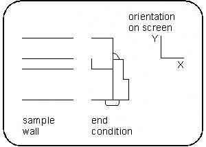
Draw a 2D symbol representing the end condition
Decide exactly what amount of detail and which parts of the opening should be included in the end condition and which should be incorporated in the opening symbol.
Clear the screen.
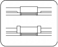
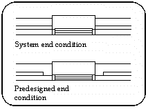
You must only create the left-hand side end condition, i.e., the wall must approach it from the left and the opening from the right. The system will create the symmetrical end condition for use on the opposite side of the opening.
The end condition is created as a conventional ARC+ drawing.
Draw the end condition on the XY plane.

Orient the end condition on screen so that if it were inserted into a wall, the wall would be parallel to the x axis (orthogonal) and drawn from left to right of the screen.
Any type of ARC+ entities except help lines are legal.
The end condition must match the layer thickness and line attributes of the wall in which it is intended to be inserted. Only that part of the wall that is changed due to the opening end condition need be included in the end condition symbol.
 HINT Create a sample wall to place the 2D opening as an aid to designing the end condition.
Add control points to the end condition using the control points (\opoint) command
Add control points to the end condition symbol as described below. See Positioning control points in an opening or end condition (\opoint).
 IMPORTANT The control points must be placed at Y=0.
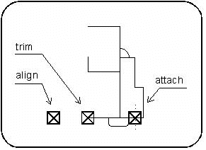
The end condition control points—each one a different color depending on your color palette—are:
|
Control Point |
Function |
|
Origin |
Controls the (y) position through the wall - aligned with the first wall layer |
|
Trim |
Cuts the wall |
|
Attach |
Positions the left and right control points of the opening |
The origin point may be superimposed over the left or right control points.
When the end condition is inserted into the wall, the wall is cut perpendicularly at the trim control point of the end condition and the left and right control points of the opening are superimposed on the attach control point of the end condition.
Sometimes you may want the end condition to overlap or penetrate the wall or opening. In such cases the control point can be located within the end condition symbol rather than at its extremities.


 NOTE You can define a universal end condition without wall layers that is suitable for all wall thicknesses and types. It must have the parameter Yw to suit it to the wall in which it is placed.
Delete the following before saving:
All help lines
All entities that are not part of the end condition symbol
Remember to delete the wall sample and opening, if you used them to help you design the end condition.
Save the end condition in the library using the Library manager (\libedit) command
Specify a name and save the end condition in a library subdirectory under the \ arcalib \end_cond directory.
It is recommended to save the end conditions for each type of wall in a separate library subdirectory named according to the appropriate wall type.
For a more detailed description, see Placed objects and libraries.
Related Topics
