Creating an Opening
Home > 06 Openings > Creating an Opening
Creating an Opening
Perform the following steps:
Draw a symbol representing the 2D opening in plan view
In advance, decide the amount of detail and which components of the opening should be in the opening symbol and which in the end condition. For example, in certain situations you may want the door frame included in the end condition while in other cases it is more appropriate in the opening symbol.
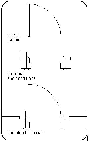
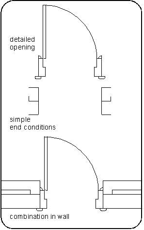
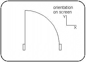
Clear the screen.
Draw the symbol (as a regular ARC+ drawing) on the XY plane only (even if it is intended for use as xz or yz presentations).
You can use any ARC+ entity to design the opening. Help lines can be used to ensure accuracy, but must be deleted before saving.
Orient the symbol so that if it were inserted into a wall, the wall would be parallel to the x axis (orthogonal)
 HINT Create a sample wall to help you orient the symbol.
 NOTE Ensure that there are no help lines or placed parametric objects in the file.
Add dimension lines to the parts of the symbol that you want to parameterize
Dimension lines must be parallel to the x, y, or z axis (orthogonal).
 HINT Use help lines and/or orthogonal mode to ensure that the dimension lines
are parallel to the major axes.
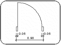
You can use multiple dimension lines, (e.g., two dimension lines — one for overall dimensions and one measuring details) but the total of the details must equal the overall dimension.
If part of the opening fits the full thickness of the wall, it is mandatory to create a wall thickness dimension line - Yw.
The actual dimensions themselves are not important at this stage; they are replaced by names in the next step.
Replace the dimension text (value) of each dimension line with a parameter name
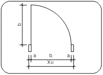
Use the Dimensions, Changing dimension text, (\dimut) command to replace the dimension text.
The name may include any combination of letters, numbers, and symbols but cannot begin with a number. Do not use spaces - use the underscore (_) instead
 IMPORTANT Certain parameter names are recognized by the system, and are reserved for specific dimensions in openings. For example, the parameter name for the wall thickness dimension in the 3D presentation must be Yw. This ensures that the opening will adjust to the thickness of any wall in which it is placed.
|
Param. Name
|
Variable
|
Use
|
|
Yw |
Variable representing the thickness of the wall into which the opening is inserted
|
3D opening and optionally in 2D
|
|
Xo |
Variable for the x axis—the width of the opening in the wall
|
2D and 3D opening
|
|
Zo |
Variable for the z axis—the height of the opening in the wall
|
3D opening, XZ and YZ sections
|
Add control points to the opening symbol using the control points (\opoint) command
 IMPORTANT The control points must be in the 2D presentation and NOT in 3D!
The opening control points—each one a different color depending on your color palette—are:
|
Control Point
|
Function
|
|
Origin
|
Controls the (y) position through the wall - aligned with the first wall layer
|
|
Left
|
Cuts the wall at the left side of the opening and attaches the left end condition
|
|
Right
|
Cuts the wall at the right side of the opening and attaches the right end condition
|
The same control points must be defined for each 2D presentation
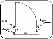
 NOTE All the control points of openings must be positioned at Y=0.
For a complete explanation of control points sees Positioning control points in an opening/end condition (\opoint) command.
Delete the following before saving:
All entities that are not part of the opening symbol (be careful not to erase the dimension lines and text)
All help lines.
Enter the Library manager (\libedit)
Choose the openings option.
Choose the save lib. option.
The library manager dialog box is displayed. Specify the following:
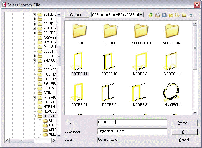
The library in which you want to save the opening symbol (path & libraries option). It is recommended to save the openings in the openings subdirectory (opening library) under the arcalib directory or open a new sub directory under openings for your library.
A name (file) for the opening and an optional description.
Press the presentation option — the Select Object Presentation dialog is displayed
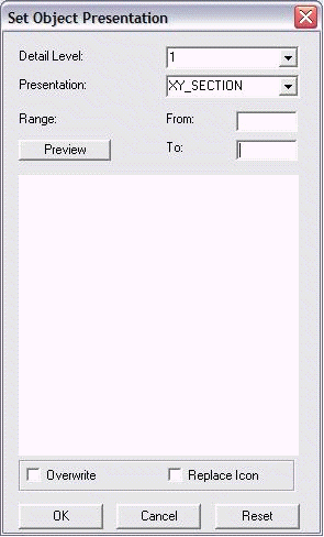
 NOTE This step is mandatory. If you try to save the opening first, this dialog box will be displayed automatically.
Choose the presentation type. Select and double-click the XY section option.
 NOTE You can create additional 2D presentations of the same opening and save them as any of the following: XY section, XZ section front, XZ section back, YZ section right, YZ section left, top view, front elev, back elev, right elev, left elev, 3D. For each 2D presentation the same control points must be used.
Set the detail level.
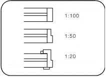
When you create an opening in a drawing that you intend to plot at a scale of 1:100, a small rectangle may be enough to represent the door frame. If you want to place the same opening in a drawing to be plotted at a scale of 1:20 a great deal more detail is required. You can create a number of presentations for the same opening, each appropriate to a different plot scale. This parameter is the scale for which the presentation was designed.
 HINT The preview function is not available at this stage, because the opening has not yet been saved. After you complete the process you can return to this dialog box and preview the presentation to confirm that your opening has been saved with the correct settings.
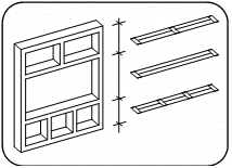
Optional—set the range for 2D section presentations
Select this option only when an opening such as a window has several different sections along its height—you can create a presentation for each of its sections. The range is the from and to coordinates within which the section is applicable.
 NOTE The system does not add or remove detail, change presentation or range automatically. You have to place or create the presentations appropriate to the scales and projections that you intend to plot or print. You can replace the presentations using the Replacing Openings (\oprepl) command.
 HINT Press the overwrite button only if you want to replace an existing presentation or detail level.
Press OK — this saves the opening in the library
You close and exit both dialog boxes.
 NOTE The process above describes the creation of a single 2D presentation on the XY plane (plan). You can create several different presentations for the same opening, e.g., for use in an XZ or YZ section. Repeat the process for each presentation, making sure to include the required parametric dimensions, saving each under the same file name and appropriate presentation name.
Create a solid for the 3D opening
The 3D opening must include a negative solid with a parameter Yw to create a void in the wall.
It is recommended to use solid prism commands such as Create Polygons— Rectangle/Box by 2 Points (\2pbox).
 HINT To ensure correct superimposition of the 3D and 2D openings, use the previously created 2D symbol as a base for creating the 3D.
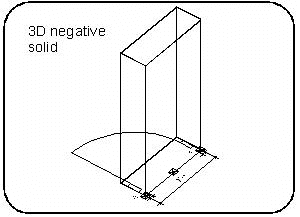
Make sure the base of the solid is at z value=0, since the height above floor is measured from the base of the wall to the Z=0 of the opening. The 3D must be located over the 2D symbol in exactly the same relationship as they will appear in the wall.
You can add both 2D and 3D positive entities to the opening to represent building elements such as window frames, sills, etc.
Orient the symbol on screen so that if it were inserted into a wall, the wall would be parallel to the x axis (orthogonal)
Any type of ARC+ entities except help lines and placed parametric objects are legal.
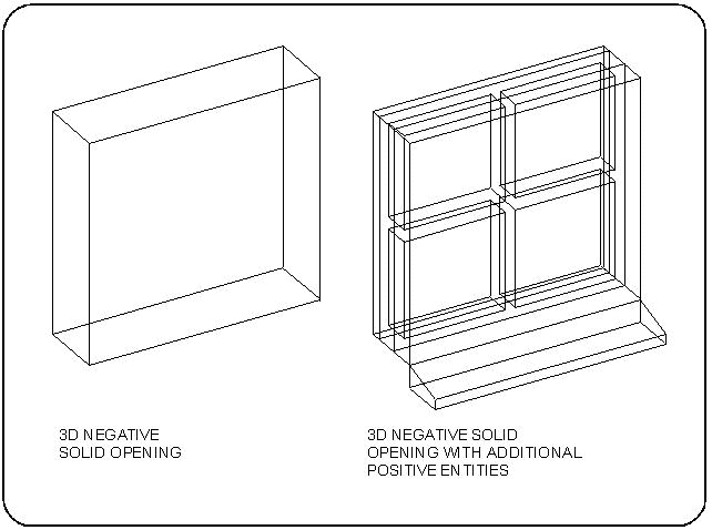
Add dimension lines to the 3D opening
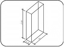
These are usually the width (x) thickness (y) and height (z), although any additional dimensions, such as the radius of an arched opening, are valid.
You can use multiple dimension lines, (e.g., two dimension lines — one for overall dimensions and one measuring details) but the total of the details must equal the overall dimension.
Dimension lines must be parallel to the x, y, or z axis (orthogonal).
 HINT Use help lines and/or orthogonal mode to ensure that the dimension lines are parallel to the major axes.
You must add a dimension line in the y axis (Yw) representing the wall thickness.
Replace the dimension text (value) of each dimension line with a parameter name
Use the Dimensions, Changing dimension text, (\dimut) command to replace the dimension text.
The name may include any combination of letters, numbers, and symbols but must not begin with a number.
 IMPORTANT Certain parameter names are recognized by the system, and are reserved for specific dimensions in openings. For example, the parameter name for the wall thickness dimension must be Yw. This ensures that the opening will adjust to the thickness of any wall in which it is placed.
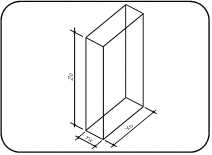
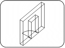
|
Parameter Name
|
Variable
|
Use
|
|
Yw |
Variable representing the thickness of the wall into which the opening is inserted
|
3D opening and optionally in 2D
|
|
Xo |
Variable for the x axis—the width of the opening in the wall
|
2D and 3D opening
|
|
Zo |
Variable for the z axis—the height of the opening in the wall
|
3D opening, XZ and YZ sections
|
Delete the following before saving:
All help lines
All entities that are not part of the opening symbol
Remember to delete the 2D symbol and its control points, if you used it to help you design the 3D opening.
Enter the Library manager (\libedit)
Use the same procedure as for the 2D opening as described above.
Specify the same library and name.
Choose the presentation option (mandatory)
Specify 3D for the presentation type.
The detail level must be the same as in the 2D opening.
Choose the OK option to save the opening
If the presentation already exists, press the overwrite button before saving. It exists if a presentation of the same detail level was previously saved for this opening.
