Positioning Control Points in an Opening or End Condition
Home > 06 Openings > Positioning Control Points in an Opening or End Condition
Positioning Control Points in an Opening or End Condition
Place control points in an opening or end condition entity.
\opoint
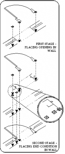
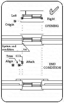
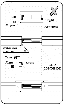
Control points determine the exact relationship between the opening and the wall and between the end condition, the wall and opening. They are represented on screen in the opening and end condition library files as small squares. There are three types of control points for openings and three for end conditions. You must place all of them to ensure correct integration of the opening and end condition. The control points are not visible when the opening is placed.
Openings
The opening control points—each one a different color depending on your color palette—are:
|
Control Point |
Function |
|
Origin |
Controls the (y) position through the wall |
|
Left |
Cuts the wall at the left side of the opening |
|
Right |
Cuts the wall at the right side of the opening |
The origin point may be superimposed over the left or right control points.
 NOTE The origin control point repositions the model of the opening so that the control point becomes the coordinate origin (0 0 0). This may cause the symbol to move off the screen. Redisplay the opening using the Plan view (\planv) command.
When an opening is placed in a wall the wall is cut at the left and right control points of the opening entity. The origin point is placed on the external line of the first wall layer.
 HINT If your opening or end condition is not positioned correctly, make sure that all the control points are placed at Y=0.
The system end condition is also located at the right and left control points.
When you add end conditions to the opening, the left and right control points are superimposed on the attachment control point of the end conditions. (See below — end conditions).
If you want the wall and opening to overlap, such as a window that slides into a recess in the wall, you can position control points that cut the wall at any position, disregarding the minimum and maximum x values of the opening.
 NOTE The control points of openings must be positioned at Y=0.
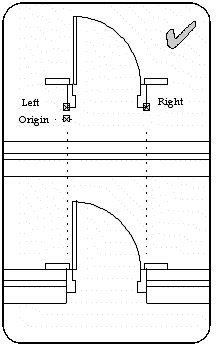
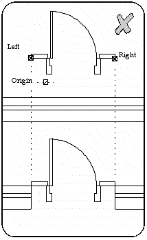
End Conditions
The end condition control points—each one a different color depending on your color palette—are:
|
Control Point |
Function |
|
Origin |
Controls the (y) position through the wall - aligns with the first wall layer |
|
Trim |
Cuts the wall |
|
Attach |
Positions the left and right control points of the opening |
The origin point may be superimposed over the left or right control points.
 NOTE The align control point repositions the model of the opening so that the control point becomes the coordinate origin (0 0 0).
When an end condition is placed in a wall, the wall is cut at the trim control point and the align point is placed on the external line of the first wall layer. The left and right control points of the opening are superimposed on the attach control points.
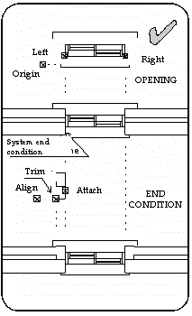
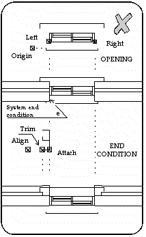
 IMPORTANT If the control points of the opening are not located at the same y=0 value as the attach control point, the opening may be relocated in the y direction (through the wall).
 NOTE You can use asymmetrical end conditions. If the attach control points of the end conditions are not the same value on the y axis, the opening is attached to the last placed end condition.
Operation
Specify whether you want to add control points to an opening or end condition.
For an opening define the positions of the origin (align), left and right points. For an end condition define the positions of the origin, trim and attach control points. To update existing control points press Enter and choose the control point that you want to update.
 NOTE Take care when snapping to control points. The exact location of the control point is the center if the square. Work at a large scale to ensure that you do not snap to the corner of the square.
