Callouts
Callouts
This command enables you to add comments to the created drawings in the form of arrow callouts.
\callout
Start by indicating all the points required to create the body of the callout or press Enter to access the settings dialog box.
Designing the callout
Indicate all the required vertices following the selected option (line, polygon, spline). If you have chosen the spline or polygon option, you can indicate as
many points as required to design the body of the callout, until you press Enter.
Click to indicate the second point defining the text direction or press Enter to give it a horizontal form.
Type text or press Enter to copy out a text already placed in the model.
Configuring the callout
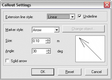
You can obtain various callout formats using the options that set the appearance of the arrows and extension lines.
|
|
|
The dialog box has two parts. The upper part manages line appearance, while the lower part configures the arrow.
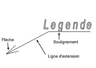
Extension line style
You can choose from three extension line styles:
|
Linear |
Polygonal |
Smoothed |
You can also choose to display the line under the text using the Underline checkbox.
Arrow settings
You can choose from three arrow types:
Arrow
|
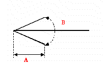
You can then set the size and angle of the arrow using the Size (A) and Angle (B) options. If you want a textured arrow, check the Solid arrow checkbox.
|
|
Placed object
Choose a two-dimensional entity in the ARC+ libraries by clicking the change object button
No arrow
In this case, the extension line does not display any symbol at its end.
After you finish the configuration, confirm with OK.


