Generating a Model with Shadows
Home > 11 Viewing > Generating a Model with Shadows
Generating a Model with Shadows
Use this command to generate a view of the of the model in a two-dimensional projection file, including colored hatch shadows as well as 3d models with shadows.
You can also:
Specify different hatch intervals for the cast shadow and shade.
Quickly redraw hatched areas.
Use a color palette for defining hatch color.
 HINT To cast a shadow on the ground you must first create a polygon representing the ground around the model.
\shadow
To generate the model;
Display your model in the solid viewing mode
Use the Generating a Model with Shadows (\shadow) command to open the Shadow Parameters dialog box. Use the dialog box to define the settings for your hatched shadow.
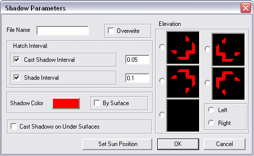
File Name
Assign a file name.
CAST SHADOW INTERVAL
Draw the cast shadow on the ground using a specified hatch interval (default—0.1m).
SHADE INTERVAL
Draw the shaded area (back-face of the building) at a specified hatch interval (default—0.15m).
SHADOW COLOR
Specify a color for the hatch (default—gray).
BY SURFACE
The hatch color is derived from the color of the surface polygon (default—off).
CAST SHADOW ON UNDER SURFACE
For use on surfaces with no thickness. Use the feature to avoid drawing shade on the underside of surfaces with no thickness (default—off).
SET SUN POSITION
Calculate the sun position (from major cities around the world), specifying the time and date or define the sun position vector coordinates. See Setting the sun position, (\sun).
ELEVATION
Rather than calculating the sun position, apply a preset sun position that cast shadows at 45° both in plan and in elevation.
There are four orthogonal preset options, and one freely-defined option for buildings that are not orientated parallel to the main axes of the system.
The preset positions are used for displaying the depth of elevations in presentations, building permission, drawings, etc. The icons indicate the shadow direction relative to the model. Choose a shadow projection by clicking the radio button to the left of the appropriate icon.
For the freely defined option, the direction of the shadow (left or right) is determined by checking the Left or Right option
Press OK. You are then prompted to provide two points on the elevation or two points exactly parallel to it, and a third point for the direction of viewing. The system calculates the shadow based on 45° to the specified line.
 NOTE Selecting an elevation option does not affect the current sun position angle.
The current projection of model with shadows is computed and saved in current directory under the file name you specified.
Use the Open an existing file (\open) command to open the file in the modeling mode. The file is displayed.
Return to the solid viewing mode and display the model using options 4 shaded surfaces or 5 monochrome shaded surfaces. You may save this image in a bitmap using the Capture the screen as a bitmap (\grab) command or High resolution pcx screen capture (\grabs) command.
Save the file as a vector file using the Saving a 2D projection of the file, (\save2D) command and open the file. You may now edit the file in ARC+. See Sample models.
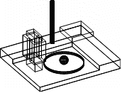
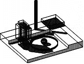
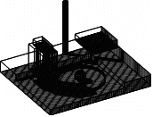
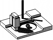
Sample Models :
|
|
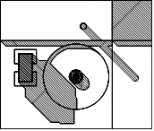
Original Model—Wireframe: |
|
|
|
|
|
|
Bottom-surfaces not shaded |
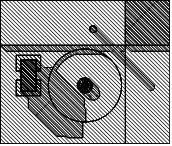
Bottom-surfaces shaded |
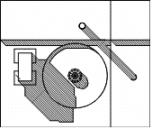
Model with Hidden Lines Removed |
|
|
|
|
|
Axonometric View |
Axonometric View |
Axonometric View |
|
|
|
|
|
Plan View |
Plan View |
Plan View |

