Entering the Solid Viewing Mode
Home > 11 Viewing > Entering the Solid Viewing Mode
Entering the Solid Viewing Mode
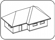
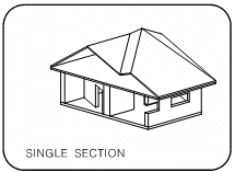
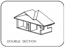
Enter the solid viewing mode for a realistic display of your model. Optionally, this command enables to view a single or double section of your model on any section plane.
You may not edit your model while you display it in the solid viewing mode.
\solid
 NOTE The solid mode options are easily accessible through the
 icon in the Modes tool bar.
Choose one of the following options:
WHOLE
Display the entire model.
SECTION
Display a SINGLE or DOUBLE of the model in any orientation.
PLAN
Display a horizontal section of the model in plan view. Specify the z coordinate of the section plane.
OPEN SOLID FILE
Open a previously saved solid model.
You can save your solid model (recommended for very large models) or press Enter to continue without saving. If you want to save the solid model later, you can use the Save a solid file (\saves) command.
You may open a model file from the solid viewing mode without having to return to the modeling mode (\geom).
If you choose the section option, see Creating a solid section below.
Your model is displayed according to the options and section planes you have specified.
To set options such as hidden lines removal, surface display, shading, and shadows, see the Setting solid viewing options (\dspmod) command
Creating a Solid Section
 NOTE The plan and section options display a section without permanently changing the model. To section or cut the entities of a model permanently, see Sectioning and sculpting.
If you choose the single section option, specify:
ORTHOGONAL
The section plane is perpendicular to the x, y, or z axis. Choose the axis. Then specify the value of the intersection point (height) on the axis, or define a point on the section plane.
DIAGONAL
The section plane is parallel to one of the axes. Define two points on the plane.
FREE
The section plane may have any orientation in space. Define three points on the plane.
In each case, indicate an additional point on the side of the section plane that is to be kept.
You are asked if you want to clear section lines. If you reply positively all lines representing contact surfaces between adjacent entities of the same color that have been sectioned, are cleared.
Use this for example when you have sectioned a model through a series of ARC+ entities that in reality would be constructed from a single monolithic material.
If you choose the double SECTION option, define the first section plane as above. Specify whether the second plane is:
PARALLEL
Parallel to the first plane. Specify the thickness of the section between the planes. The second plane always lies between the origin (0, 0, 0) and the first plane.
NON PARALLEL
Define the second plane in the same way as the first.
You are asked if you want to clear section lines. If you reply positively all lines representing contact surfaces between adjacent entities of the same color that have been sectioned, are cleared.

Use this for example when you have sectioned a model through a series of ARC+ entities that in reality would be constructed from a single monolithic material.


 NOTE If you display a section, you can rotate the view to a direction that is perpendicular to the section plane (see Viewing a section plane, \vsect) command.
