Copy On Path
Home > 15 Placed Objects and Libraries > Copy On Path
Copy On Path
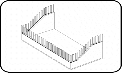
You can copy objects along the path defined by any 2D or 3D polygon using this command. This can prove to be particularly useful to model architectural tools like handrails and fencing.
\copyp
 IMPORTANT: Only placed objects can be used to copy on a path.


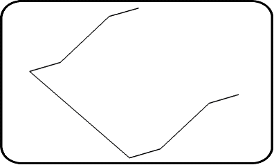
A polygonal path
Elements copied along the path
A menu with the following options appears after you run this command:
Create / Modify a polygon series
Copy series from another polygon
Transfer series from one polygon to another
Unlink series from the polygon
Remove polygon elements
Regenerate a polygon
Create / Modify a polygon series
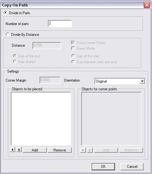
This option enables you to indicate a polygon to be used as a path and displays the Copy On Path dialog box:

There are only two ways to divide a path, by number of equal parts or by distance. This dialog box has 3 parts:
Divide in parts,
Divide By Distance
Parameters.
The first two parts contain parameters specific to the two methods while the last one shows parameters common to the two methods.
Divide in Parts
The Divide in parts section of the dialog box refers to dividing the path by a specific number. The only parameter to be changed here is the number of divisions.
 NOTE: If a path is divided in 2 parts, it amounts to copying 3 elements: one at the beginning, one in the middle and one at the end.
Divide By Distance
The Divide by distance section of the dialog box contains more options. The main option is the distance between each object, which will automatically determine the number of objects to be placed on the path.
We face two problems by entering an approximate distance:
A portion of the path cannot be used because of lack of space.
The elements to be copied cannot be inserted in the corners of the path.
These problems cannot be resolved, but can be controlled by using one of the options:
|
OPTION |
DESCRIPTION |
|
Gap at… |
With the Space option, you can decide where to place the unused space. Using this option, you can define the space at the end of the path, at the beginning or divided between the beginning and the end. You can also divide this space between all the elements by choosing the Shared option. |
|
Force Corner Points |
With this option, the command will force the placing of an object at every corner of the path. |
|
Bisect Mode |
With this option, you can place elements according to the bisector of every corner of the path |
 IMPORTANT: If you choose the "Shared" option, the distance between the elements will be automatically rescaled and may not correspond to the value entered in the Distance range.
Parameters
The Parameters section of the dialog box includes the list of objects to be placed on the path. There are two lists:
The Objects to be placed list is the list of objects that are to be placed while copying.
The Objects to be placed at the corners list is the list of objects that are to be placed at the corners.
 NOTE: When the "Objects to be placed" list contains the name of at least one object, the active or inactive status of the "Force Corner Points" option has no effect on the result. the command recognizes the corners and uses this special list to select the objects that are top be placed here. If the "Objects to be placed at the corners" list is not used, the command then uses the objects only from the "Objects to be placed" list, and when the "Force Corner Points" option is activated, the system will use this list for the objects that are to be placed at the corners as well.
You can add objects to the lists using the Add buttons and remove them by using the Remove buttons. While placing objects on the path, the command will switch objects according to the order in which they appear in the lists. You can change this order by using the following two buttons:

The other options of the Parameters section of the dialog box are explained below:
Orientation
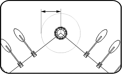
This option gives the command the orientation for placing the objects. The Original option will use the default orientation of the objects while the Parallel and Perpendicular option will orient the objects parallel or orthogonal to the path respectively, as shown in the figure below:

Margin
This option gives the command the minimum length of the range around every corner in which there is no object, except for those of corners

Changing series
The series of objects thus created will have a permanent connection with the polygon. This means that any change in the shape or position of the polygon will be reflected on the attached elements. You can also change the parameters of a series by applying this command again on the polygon as path. This will reopen the Copy on Path dialog box with all the present parameters and object of the series.
Copy series from another polygon
This option enables you to copy the parameters of an existing series to a polygon, all the selected, polygons or all the polygons in the model.
Transfer series from one polygon to another
This option enables you to move the parameters of an existing series to a polygon, all the selected, polygons or all the polygons in the model. Following this action, the original polygon containing the series becomes a normal polygon again.
Unlink series from the polygon
This option is used to delete the connection between the polygon as path and the objects of the series. The polygon then becomes a normal polygon again.
You can apply this action to a polygon, all the selected, polygons or all the polygons in the model.
Remove polygon elements
Unlike the Unlink option the Remove option not only removes the connection between the polygon and the objects but also removes the objects placed on the path.
You can apply this action to a polygon, all the selected, polygons or all the polygons in the model.
 NOTE: Once you use the "Unlink" or "Remove" options, it is impossible to change the previous parameters because they are deleted with the connection between the objects and the polygon.
Regenerate a polygon
This option is used to rebuild the connection between the polygon as path and the placed objects after the polygon has been moved or its shape has been changed.
You can apply this action to a polygon, all the selected, polygons or all the polygons in the model.
