Setting and Updating Attributes
Home > 19 Dimensions > Setting and Updating Attributes
Setting and Updating Attributes
The dimensions are managed by styles, there are two toolbars:
- Short
This toolbar alows to set the current dimension style.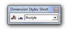
The first icon allows to change all parameters of the dimension style.
The second icon sets the current style to one entity or to the selection group.
The pull down menu allows to select the current dimension style that would be used to create a new dimension. - Extended
This toolbar alows to set the main parameters.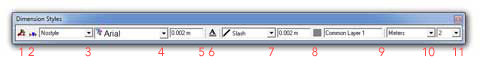
1. Allows to change all parameters of the dimension style.
2. Sets the current style to one entity or to the selection group.
3. The pull down menu allows to select the current dimension style that would be used to create a new dimension.
NOTE: Options 4 - 11 are only available when the dimension style is set to nostyle.
4. Sets font of the text dimension
5. Size of text dimension (in Meter)
6. Colour of text dimension
7. Tick mark setting
8. Size of tick mark
9. Colour of dimension line
10. Unit of text dimension
11. Decimal of text dimension
Set the attributes of dimension lines and text.
\uadim
You can select entities to update with the current dimension style.
\adim
Set dimension attributes of the Dimension Style withe dialogue box as shown below.
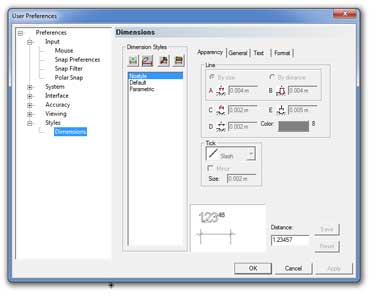
It consists of 4 tabs Appearance, General, Text, Format. The details of their contents are given below.
General Attributes (General tab)
The parameters of the Appearance tab are:
|
Attribute
|
Description
|
|
line
|
Choose to set the length between an entity and base of the extension line by size (fixed length) or by distance (offset)
By size
By Distance
|
|
Color: Click on the color rectangle to access the color selector. |
|
|
|
|
|
|
|
|
|
|
|
Tick
|
Choose: slash, circle, arrow, object
|
|
Mirror: Horizontal Reflection of tick |
|
|
|
|
|
color of the dimension line
|
Click on the color rectangle to access the color selector. You can choose between the 255 colors of ARC+. Click on the color of your choice and then click OK to select it.
|


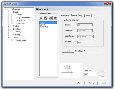
The parameters of the general tab tab are:
|
Attribute
|
Description
|
|
entities to dimension |
Choose between the three options: all, walls only (wall entities only) or selection (selected entities only)
|
|
openings |
You can specify how wall openings should be dimensioned: none: do not dimension openings + width: indicate width only +height: indicate width + height +Sill Ht. indicate the width + height + sill
|
|
wall details
|
Dimensions of wall faces, wall axes, or both
|
|
Sill label |
Set label text (e.g. Sill=) if any |
|
LAYER
|
You can click the Layer... button to set the default placing layer of dimensions. This will open the following layer selector below.
If you want the dimensions to be placed on the current working layer instead of the specified layer, click on the Current button. |


Setting Wall Elements for Dimensioning
The entities to dimension parameters determine the type of entities to dimension - all entities, walls only, or the openings also. You also specify which wall details to dimension—faces, axes, or both. When you dimension openings, you can include:
Width
Add height of the opening
Add sill height
(You can specify a label of up to five characters for the sill height, for example Sill=or the abbreviation S. Remember to add a space character if you want a space between the tag and the sill dimension).
When you dimension walls, the system uses the parameters you set to create a dimension line from wall ends, at junctions with walls as well as openings (if you chose this option). If you set a dimension line along wall faces, and the two sides of the wall are of unequal length, the side closer to the dimension line is dimensioned. Dimensions of a T-junction are displayed when the dimension line is on the same side of the wall as the junction.


sill


 NOTE The sill is not displayed if its height is zero.
The parameters of the text tab tab are:
|
Attribute |
Description |
|
Font |
Choose the name of the font of caracters (see Setting text attributes (\atext)) |
|
Style: Italic, Bold |
Display parameters of the caracters (Font TrueType™ only) |
|
Justification |
Horizontal alignment of text when it is too large to fit in between the two extension lines. |
|
Location |
Vertical alignment of text with respect to the dimension line |
|
Color |
Click on the color rectangle to access the color selector. You can choose between the 255 colors of ARC+. Click on the color of your choice and then click OK to select it |
|
Height |
Text size |
|
Text mode |
fixed or scaled |
|
proportional |
Specify text spacing by entering a value from 1 to 32: proportional distance between characters |
|
Width of text |
Indicate value greater than 0.1 (ARC+ fonts only) |
|
Slant |
Set text angle between -45 and +45 (ARC+ fonts only) |
You can also customize the automatic repositioning of the dimension text. To display the Automatic Repositioning dialog box, click the Parameters... button.
 HINT: Refer to the chapter 19 of volume 2 to familiarize yourself with the automatic repositioning parameters.
Dimension format (Format tab)
The third tab manages the format of the dimension text.
|
Attribute |
Description |
|
Unit |
Measurement unit: millimetres, centimetres, or metres; decimal inches or feet; feet & decimal inches; fractional inches; feet & fractional inches. |
|
Accuracy Preferences |
Number of digits displayed after the separator. This parameter concerns all the decimal dimensions (millimetres, centimetres, metres, foots, decimal inches). |
|
Display trailing zeros |
Activated, the trailing zeros are displayed. e.g. 1.500 instead of 1.5, if the accuracy is of 4. |
|
Mix meters and centimeters |
This parameter concerns the meter unit only. Activated, the zero of the whole part is not displayed if the distance is less than 1 meter. e.g. 5 instead of 0.5 for 50 cm |
|
Display zero inches |
Activated, displays zero inches. e.g. 1’ 0/16’’ instead of 1’. |
|
Fraction |
Controls the fractional accuracy. The permitted values are: none, 1/2, 1/4, 1/8, 1/16, 1/32 or 1/64. This parameter can be used for the fractional units only (feet, inches). |
|
Extra accuracy |
Enables the display of additional digits after the separator for the accuracy certain values. The permitted values are:.01, .25, .5, .1, Off. These digits are displayed in superscript. e.g. 30.55 |
|
Big superscript digits |
Controls the type of superscript for additional accuracy. (ARC+ font only). |
|
Sill on the wall |
This parameter enables to decide whether the sill label (e.g.: sill=90) should be placed close to the wall (checkbox checked) or close to the dimension (checkbox unchecked) |
|
separator |
Choose dot or comma |
Automatic Repositioning by Settings
When you dimension entities automatically, there may certain situations in which there is not enough room to locate all of the dimension text on the line. If a dimensioned segment is too short to insert the text (according to the current settings), the system will automatically align the text differently from the settings—for example, to the right or up instead of centering it. A new option enables you to control the priorities used by the system to relocate the text (refer to priority settings in table above).
Operation
In the Dimension Attributes dialog box choose the text settings option. Use the text location and priority options in the Dimension Text Attributes dialog box to set the parameters for placing dimension line text. To display the Setting Automatic Reposition dialog box choose the automatic repositioning option.

In cases where text will not fit on the dimension line, you can set up to four priorities for text displacement. The system will attempt to reposition the text according to the priorities.
If the text cannot be repositioned according to any of the settings, it will be displayed in a different color (indicating that it is overwritten by adjoining texts).
When Automatic Repositioning is on, it overrules the location and priority settings.
When the automatic repositioning option is off, text is displaced according to the priority selection in the Dimension Text Attributes dialog box: left, center, or right. (See Moving dimension text command \dimmt.)