Import Parameters
Home > 10 Files > Import Parameters
Import Parameters
Certain parameters are required to be defined before DXF/DWG conversion to maintain the compatibility of the converted files with ARC+:
Scales and Unit
Reference Point
Line Width
Line Type
Layer
Font
Colors (if any)
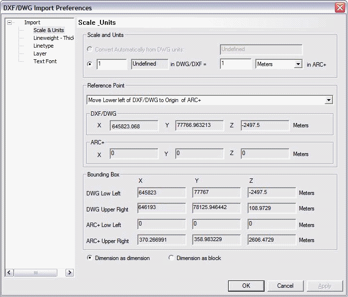
These parameters can be defined with the help of following dialogue box:
 IMPORTANT: Other parameters and objects such as the dimensioning, motifs and hatching are converted automatically by the system into ARC+. These parameters are transformed into blocks to ensure the graphic compatibility with the original file.
Scale and units
The Scale and unit section in the dialogue box helps you to define new scale for your file and define its units.
Two options are available for the conversion of scale and units :
 Automatic conversion of DWG units – the field on right displays the units used in DWG files. This option is selected by default if the unit defined for the DXF/DWG file is one of the following: meters, centimeters; millimeters, inches, foots. The units used in the DXF/DWG files will be converted automatically to meters.
 Conversion of DWG units to new units – with this option you can define the relation between the original design units and the target file. For example you can define that one DWG unit should be equal to 4 centimeters. This option can be used only for conversion of a DWG file without units.
 IMPORTANT: ARC+ cannot interpret correctly a model of exceeding the size limits of 0.00001 to 99999.999m. If the DXF/DWG files to be converted contain a model exceeding the size limits, you have chosen a scale factor to adjust the model size.
Reference point
You can use this section to shift the model from its original location to a new location in the converted file. There are various possibilities for shifting a model:
Origin point of DXF/DWG matches with ARC+: By default, this option is defined. If this option is selected, ARC+ will place the point (0, 0, 0) of DWG file on its own point (0, 0, 0) (origin on origin).
Shift the lower-left corner of the DXF/DWG file towards the origin point of ARC+ file: This option is functional when the DXF/DWG design contains the coordinates exceeding a value of 99999.999m. ARC+ will place the lower-left corner of the DXF/DWG file on its origin point (0, 0, 0). This option is defined by default when the enclosing box of the DXF/DWG design to be converted, contains a coordinate larger than 99999.999m.
Shift the upper-right corner of the DXF/DWG file towards the origin point of ARC+ file: This option is useful when the location of the origin point of the source file is not important and its content is far from point (0, 0, 0) ARC+ will place the upper-right corner of the DWG file on its origin point (0, 0, 0).
Shift manually the lower-left corner of the DXF/DWG file to the point: you can use this option to specify precise coordinates on the grid of the ARC+ file on which the lower-left point of the DXF/DWG file should be shifted. Use X, Y, Z fields to define the coordinates of the point (For example: -22.3, 5, 21.6).
Shift manually the upper-right corner of the DXF/DWG file to the point: you can use this option to specify precise coordinates on the grid of the ARC+ file on which the upper-left point of the DXF/DWG file should be shifted. Use X, Y, Z fields to define the coordinates of the point (For example: -22.3, 5, 21.6).
Shift manually the origin of the DXF/DWG file to the point: You can use this option to shift the origin of your DXF/DWG file to a point specified in the work area of ARC+ file. Use X, Y, Z fields to define the coordinates of the point.
Shift manually the specified point of the DXF/DWG file to a specific point of ARC+ file: You can use this option to specify a point in the DXF/DWG file that you want to shift to a point specified in the work area of the ARC+ file. Use X, Y, Z fields to define the coordinates of the point.
Enclosing box
You can use this section to adjust the size of the design-enclosing box in the DXF/DWG file as well as in the target ARC+ file. Note that the dimensions of the enclosing box can be altered by the values entered in the Reference point and Scale and units sections. ARC+ calculates automatically the X, Y, Z coordinates of the limits of your model.
 IMPORTANT: The coordinates are calculated as per the specified ARC+ unit.
Line width
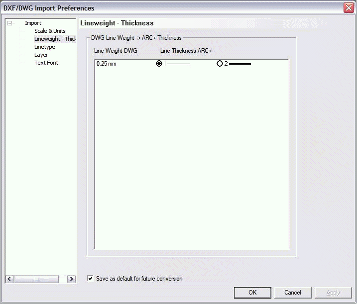
Certain CAD software offer several line widths available in display in work mode. The work area of ARC+ offers two line widths – Thin (1) or Thick (2) – to facilitate its usage. You can define the line width for print in the print manager depending on the color of the line. With the DXF/DWG converter, you can easily define line width (1 or 2) in ARC+ file, which will be attributed to the lines in the DXF/DWG file. Click on line width to display the following dialogue box:
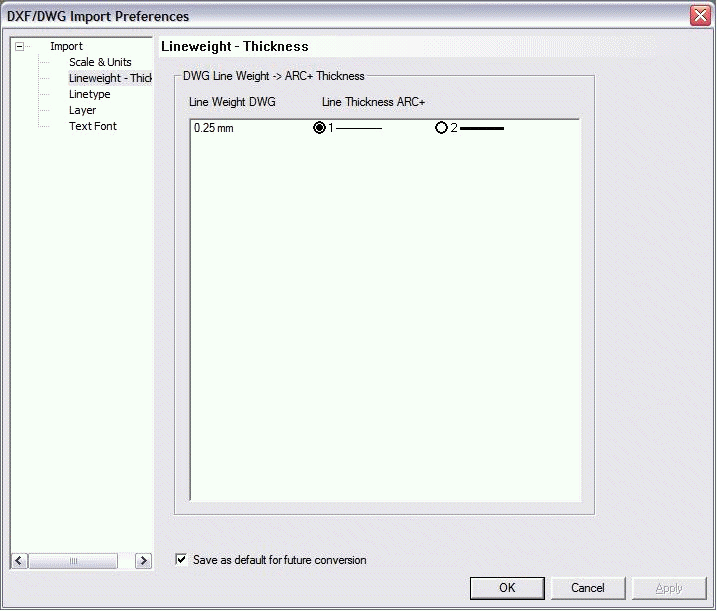
The line widths used in the DXF/DWG files are displayed on left under DWG line width.
The line widths available in ARC+ (1 and 2) are displayed on right under ARC+ line width. The line widths are given in two columns with the corresponding option buttons.
You can select an ARC+ width for every width of DXF/DWG origin using the corresponding option buttons. For example , if you select the line width of 0.00 in DXFD/DWG for the line width "1" in ARC+ file, the display will be:

If you select the width "2" in ARC+ file for the line width of 0.25 in DWG, the display will be:

You can define the parameters that will become the default parameters for the future conversions. You can do it by checking the Save as default for other conversions option.
Line Type
ARC+ offers a choice of 7 different line You can convert all types of lines in DXF/DWG file to a line type in ARC+. For this, use the Line type section in the Preferences dialogue box:
The line types in DXF/DWG files are displayed under DWG line types.
The Description part of the dialogue box gives you view of DWG/DXF line types as per their original display.
In the Line type part of the dialogue box, with the help of a pulldown menu, you can select an ARC+ line type to which the DWG/DXF line will be converted.
You can define the parameters that will become the default parameters for the future conversions. You can do it by checking the Save as default for other conversions option.
 NOTE: You can add new line types that will be identified and displayed in the Description section. Open the arcplus.lin file (using Wordpad) and paste the new line types here from other CAD software. Access the arcplus.lin file from: ARC COMPONENTS/Library/Line types.
Layer
In ARC+, you can reorganize the layers from the DXF/DWG files while giving them the numbers of your choice. You can use numbers from 1 to 255 excluding 99 (this number is reserved for help line). The names given to original layers of DXF/DWG files are displayed in the ARC+ layer manager after conversion.
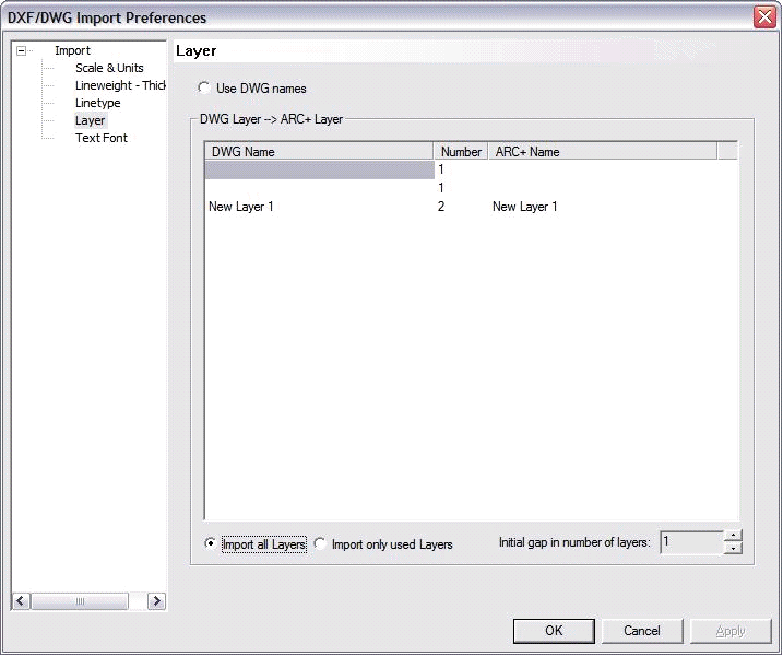
The names of the layers from DXF/DWG file are displayed in the Name section of the dialogue box.
You can change the layer numbers (from 1 to 255, except 99) in the Number section.
If you give the same number to two original layers from the DXF/DWG file, the two layers will be merged automatically.
Check the Import all layers option if you wish to import all the layers defined in the original DXF/DWG file even if they are empty.
Check the Import only used layer option if you want ARC+ to ignore the empty layers while importing.
ARC+ does not have "0" layer. If the first layer in the DXF/DWG file is "0", you can specify the starting layer for offset while converting. In this design, enter the layer number in the Shift 1st layer field.
Font
ARC+ converts the DXF/DWG fonts to ARC+ native fonts or to TrueType fonts. You can view and modify the fonts using Font dialog box, accessible from DXF/DWG Import Preferences dialog box:
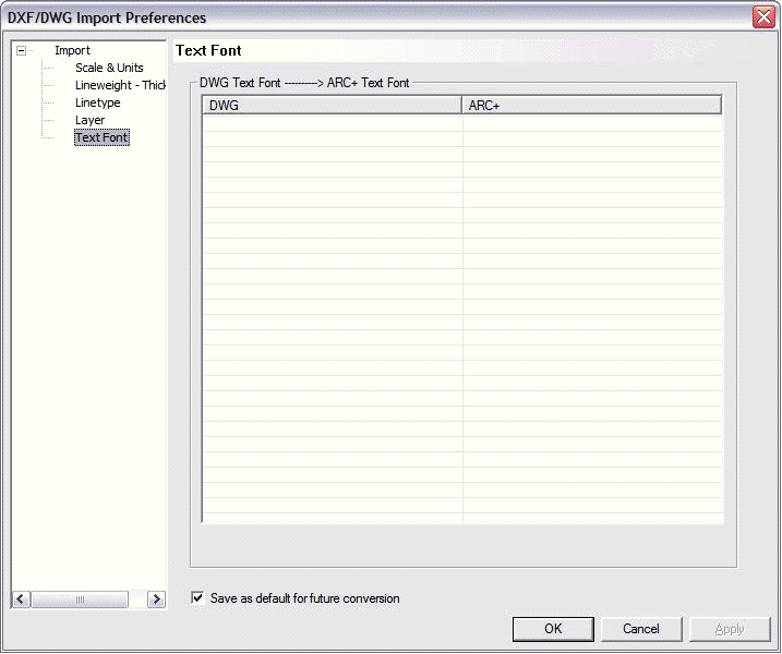
The fonts from DXF/DWG file are displayed at left under DWG. Extensions of these fonts are .shx (native) or .ttf (Windows TrueType).
You can change the defined fonts from the ARC+ section at right. You can select .ttf (Windows TrueType) or .fon (native ARC+) fonts to replace the fonts from DXF/DWG file. Click on the original font name and use the pulldown menu to apply the font of your choice.
You can define the parameters that will become the default parameters for the future conversions. You can do it by checking the Save as default for future conversions option.
Colors
If you have given the \cuscolor command to modify 2 to 15 ARC+ colors, the color category will be added automatically to your DXF/DWG conversion manager.
If you have not changed 2 to 15 colors to 255 color palette, ARC+ recovers automatically the corresponding 255 colors of DXF/DWG.
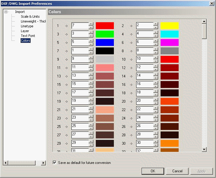
The numbers 1 🡪 ; 2 🡪 etc. represent the 255 DXF/DWG colors; the colored boxes are the graphical representations of these colors.
Between the numbers (1 🡪 ; 2 🡪…) and the colored boxes, there are fields representing the 255 ARC+ colors; you can change these numbers.
Use the buttons or enter a new value to specify the number of the new color that you want to integrate instead of the corresponding DXF/DWG color.
Click OK to validate your selection.
You can define the parameters that will become the default parameters for the future conversions. You can do it by checking the Save as default for future conversions option.
