Export Parameters
Home > 10 Files > Export Parameters
Export Parameters
In order to maintain ARC+ compatibility of the converted file, you should define certain parameters before exporting to DXF/DWG formats:
Scales and Unit
AutoCAD® version
Reference Point
Line Width
Line Type
Font
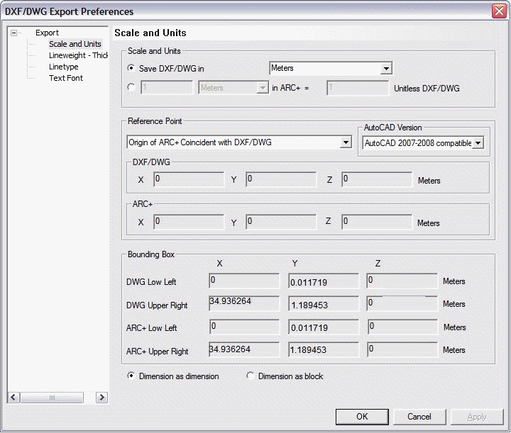
Scale and Units
You can define the scale of your converted model in this section. You can use the scale set in the ARC+ source file for the target file. Check the first option in the Scale and units section:
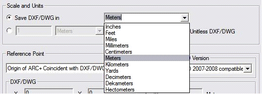
Select the target unit for DXF/DWG file from the pulldown list.
You can set "No unit" scale for the target DXF/DWG file by selecting the second conversion:

You can use this section to set the scale value as "No units" for the target DXF/DWG file. For example, you can define one meter in ARC+ as equal to ten units of "No units" scale of the DXF/DWG file or two centimeters equal to 5 "No units" etc.
AutoCAD® Version
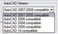
In ARC+, you can select various versions of AutoCAD® for file conversion. It is recommended to customize your file as per the version of AutoCAD® or that of any other CAD software in which it will be opened. For example, you cannot open a file meant for AutoCAD® 2000 if it was saved as an AutoCAD® 2008 file. If you do not know in which version of AutoCAD® or CAD software the file shall be opened, select "Compatible AutoCAD® 14".
Reference point
You can use this section to shift the model from its original location to a new location in the converted file. There are various possibilities for shifting a model:
Origin point of ARC+ matches with DXF/DWG: By default, this option is defined. If this option is selected, the system will place the point (0, 0, 0) of ARC+ file on the point (0, 0, 0) of DXF/DWG file (origin on origin).
Shift the lower-left corner of the ARC+ file towards the origin point of DXF/DWG file: This option is useful when the location of the origin point of the source file is not important and its content is far from point (0, 0, 0) ARC+ will place the lower-left corner of the source file on the origin point (0, 0, 0) of DXF/DWG file.
Shift the upper-right corner of the ARC+ file towards the origin point of DXF/DWG file: This option is useful when the location of the origin point of the source file is not important and its content is far from point (0, 0, 0) ARC+ will place the upper-right corner of the source file on the origin point (0, 0, 0) of DXF/DWG file.
Shift manually the lower-left corner of the ARC+ file to the point: You can use this option to specify precise coordinates on the grid of the DXF/DWG file on which the bottom-left point of the source file should be shifted. Use X, Y, Z fields to define the coordinates of the point (For example: -22.3, 5, 21.6).
Shift manually the upper-right corner of the ARC+ file to the point: You can use this option to specify precise coordinates on the grid of the DXF/DWG file on which the upper-right point of the target file should be shifted. Use X, Y, Z fields to define the coordinates of the point (For example: -22.3, 5, 21.6).
Shift manually the origin of the ARC+ file to the point: You can use this option to shift the origin of your source file to a point specified in the work area of the DXF/DWG file. Use X, Y, Z fields to define the coordinates of the point.
Shift manually the specified point of the ARC+ file to a specific point of DXF/DWG file: You can use this option to specify a point in the ARC+ file that you want to shift to a point specified in the work area of the DXF/DWG file. Use X, Y, Z fields to define the coordinates of the point.
Enclosing box
You can use this section to adjust the size of the design-enclosing box in the ARC+ file as well as in the DXF/DWG target file. Note that the dimensions of the enclosing box can be altered by the values entered in the Reference point and Scale and units sections. ARC+ calculates automatically the X, Y, Z coordinates of the limits of your model.
 IMPORTANT: The coordinates are calculated as per the specified DXF/DWG unit.
Line width
You can use this section to specify a DXF/DWG width for each of the two ARC+ widths.
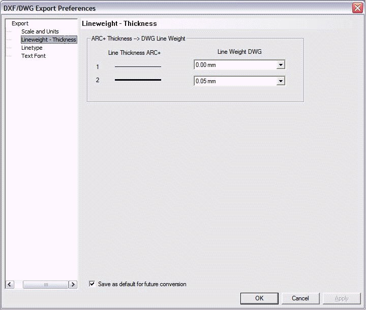
You can use the pulldown menu of DWG line width to assign the DXF/DWG line widths used for the conversion.
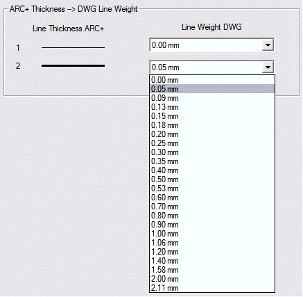
You can define the parameters that will become the default parameters for the future conversions. You can do it by checking the Save as default for future conversions option.
Line type
You can convert seven ARC+ line types into DXF/DWG line types using Line type section of the Export preferences dialog box:
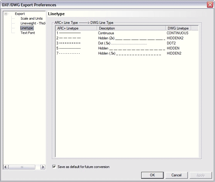
ARC+ Line type displays the ARC+ line types. You can use the pulldown menu of the Description section to select the DXF/DWG line types that will replace the ARC+ line types:
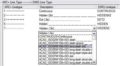
DWG Line type displays the conventional names of DXF/DWG line types.
You can define the parameters that will become the default parameters for the future conversions. You can do it by checking the Save as default for future conversions option.
 NOTE: you can add new line types that will be identified and displayed in the Description section. Open the arcplus.lin file (using Wordpad) and paste the new line types here from other CAD software. Access the arcplus.lin file from: ARC COMPONENTS/Library/Line type.
Font
You can use the Font section of the Export preferences dialog box to convert the fonts of your model into other fonts, TrueType or .shx, in the DXF/DWG file section.
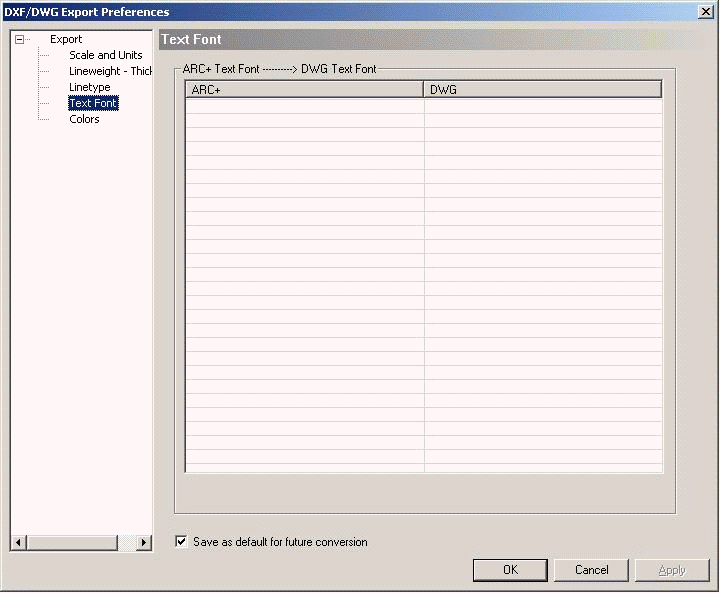
You can use the ARC+ section of the dialog box to view the fonts from ARC+ source file.
You can use the DWG pulldown menu to select the font that will replace the source font after the conversion:

Click "Other…" to open the Open dialog box; you can browse through the locations on your computer to find the new text styles to integrate in your list (for example, .shx fonts that you will have on your computer if you have installed AutoCAD®):
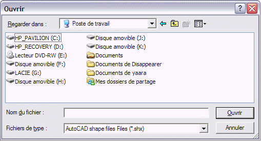
You can define the parameters that will become the default parameters for the future conversions. You can do it by checking the Save as default for future conversions option.
Colors
If you have given the \cuscolor command to modify 2 to 15 ARC+ colors, the color category will be added automatically to your DXF/DWG conversion manager.
If you have not changed 2 to 15 colors to 255 color palette, ARC+ recovers automatically the corresponding 255 colors of DXF/DWG.
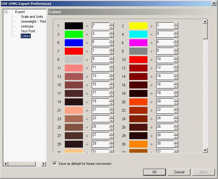
The numbers 1 🡪 ; 2 🡪 etc. represent the 255 ARC+ colors. The colored boxes are the graphical representations of these colors.
At the side of these colored boxes having the colors of your ARC+ model, you will find the fields representing the 255 DXF/DWG colors. You can change these numbers.
Use the buttons or enter a new value to specify the number of the new color that you want to integrate instead of the corresponding ARC+ color.
Click OK to validate your selection.
You can define the parameters that will become the default parameters for the future conversions. You can do it by checking the Save as default for future conversions option.
Dimensions

Depending on the need of your third party you can decide to export dimension as real dimensions or as blocks.
Choose "dimension as dimension" ONLY when your third party really needs to adjust in his cad the dimensions. Your drawing must contain one scale only to be correct. So it cannot not contain scaled images and different scales like in most cases dsg sheet files. It will surprises and error for sure to the third party when you scale real dimensions.
.Choose Dimension as block in most cases where you just want to show the third party with surely the same look in his cad as in arc+.
