Creating a Linear Pattern between Two Parallel Lines
Home > 08 Hatching Patterns > Creating a Linear Pattern between Two Parallel Lines
Creating a Linear Pattern between Two Parallel Lines
Create a linear pattern between two parallel lines.
\2lpat
The linear patterns must be created in one of the orthogonal views (XY, YZ, and XZ planes) and are not displayed in any other view.
Choose a linear pattern via the pull-down graphic library or by specifying its code (a single ascii character). Specify the color for the pattern. Indicate the lower and upper parallel lines.
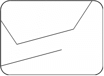
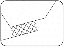
Where the lines are not of equal length, the pattern is created only between the parts of the lines that are opposite each other. The linear pattern is scaled and, therefore, will always maintain its relative size between these two lines.


 NOTE Pattern definitions a to s are provided with the system. They reside in the font file called arcpatrn in the arcalib\fonts directory.
You can update existing patterns or add your own patterns using the Font editor (\fonte) command. Specify the font file arcpatrn.
 HINT For this function it is recommended to select only the full height linear patterns from the library.
The parallel lines can be a straight segment of any type of entity, such as a line, polygon, wall, help line or placed object.
