Convert 2D polygon to 3D path
Home > 04 Polygons and Solids > Convert 2D polygon to 3D path
Convert 2D polygon to 3D path
You can use this command to create from the plan view of a path (drawn with a 2D polygon), a corresponding path in 3D space.
\pol3d
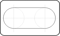
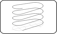
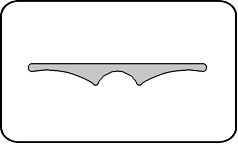
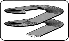
This path is obtained while controlling its overall slant or the slant of every segment. The result thus obtained can be used subsequently to extrude a profile along the path to generate the "access ramp" elements as shown in the following illustration:
|
|
|
|
2D Polygon |
Result of conversion to 3D path |
|
|
|
|
Profile |
Extrusion result |
After running this command, indicate the polygon to edit or press Enter to convert a 3D path back to 2D polygon. The entity you indicate is therefore a polygon (or an arc) or a 3D path created previously by the same command.
 IMPORTANT: If the indicated entity is not a 3D path, make sure that all the points of the polygon or arc are on the same plane as that of the z level. This polygon (or arc) may be open or closed; it is possible to extend the 3D path repetitively only if it is closed.
Following dialogue box will appear:
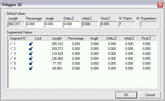
The following paragraphs describe all the parameters displayed in this dialog box and the different operating modes to set or change the overall slant of the path or the slant of each of its segments.
Click OK to apply the changes.
 NOTE: The displayed values are shown in the current working unit.
Global values
The parameters displayed in the Global values box of this dialog box to view or change the values that can be applied to the 3D path or to the unlocked segments in the grid of the Segmented Values.
|
VALUE |
DESCRIPTION |
OPERATION |
|
Length |
Displays the total length of the resulting 3D path. |
You cannot change this value. |
|
Percentage |
Defines the overall slope of the 3D path or changes the slope of all the unlocked segments. |
You can enter a value and press TAB. Changing these values changes the slant of all the segments of the 3D path that are unlocked in the grid of Segmented Values. You can enter a positive value to make a path ascending or a negative value to make a path descending. |
|
Angle Help Lines |
||
|
Delta Z |
Defines the total height described by the resulting 3D path. |
|
|
Initial Z |
Displays the departure height of the 3D path. It corresponds to the initial level of the polygon. |
You cannot change these values. |
|
Final Z |
Displays the arrival height of the resulting 3D path. |
|
|
Points |
Displays the number of total points of the polygon of the resulting 3D path. |
|
|
No. Repetitions |
Defines the number of repetitions of the path. This value is accessible only when the indicated entity is a closed polygon or arc. |
You can enter a value and press TAB. Changing this value allows extending the 3D path by several identical repetitions. |
Segmented Values
The grid in the Segmented Values box displays a line for every polygon segment to edit.
Move the dialog box to the side of the screen and click on different lines of the grid. You can find that the corresponding segment is displayed in a temporary orange highlight.
Segment type
One of the following three icons appear to help you identify easily the concerned segment type:
 Linear segment
 Circle arc segment
 Curve segment
Locking
The Lock column displays an icon indicating if the slope of the corresponding segment can be changed or not while you are modifying the global values in the Global values box. You can exclude some segments from these global modifications in order to modify them separately. You can do it by double clicking on the lock icon so that it shows "locked":
|
ICON |
DESCRIPTION |
|
|
The corresponding segment is controlled only by the global modifications. |
|
|
The corresponding segment no longer undergoes the global modifications. You can change its settings for Length, Percentage, Angle or Delta Z. |
Parameters
The following table describes the other parameters displayed in the Segmented values grid columns: In order to change the settings of a segment, double click on its value while making sure that this segment was "locked" earlier.
|
VALUE |
DESCRIPTION |
OPERATION |
|
Length |
Displays the total length of the segment. |
You cannot change this value. |
|
Percentage |
Defines the slope of the segment. |
You can change these values only if you have protected the corresponding segment from global modifications by "locking" them. You can enter a positive value to make a segment ascending or negative value to make it descending. |
|
Angle |
||
|
Delta Z |
Defines the total height described by the segment. |
|
|
Initial Z |
Displays the departure height of the segment. |
You cannot change these values. |
|
Final Z |
Displays the arrival height of the segment |

