Cameras
Home > 11 Viewing > Cameras
Cameras
Add a New Camera
To add a new camera, you have to first display the model following the view that you want using the regular ARC+ view control windows or commands. Then click on Add new in the Cameras tab.
Camera Settings
When you add a new camera, the Manager doesn't save only the view coordinates(eye, target, perspective cone) but also the following information:
The present 2D/3D mode
The display mode (enables GEOM, SOLID+hidden lines, colored surfaces, etc…)
The orthogonal/perspective view
Hatches/patterns visibility
Layer configuration
Scale mode
Auto clip on/off
Line merge on/off
Preserve walls on/off
Save 2D overwrite on/off
Remove coinciental lines on /off
Preserve XY dimension on/off
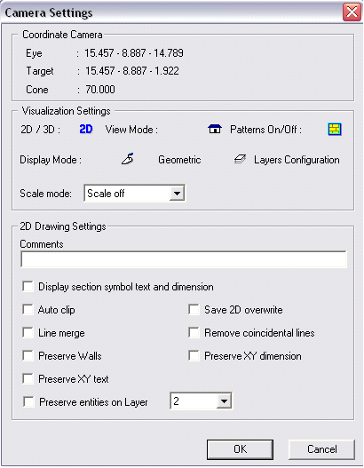
You can access all these settings by double clicking on the name of a camera in any tab of the Manager, which opens the Camera settings dialog box:

This dialog box has 3 parts:
Coordinate Camera
Visualization Settings
2D Drawing Settings
Coordinate Camera
You can see the coordinates of the saved camera in the upper part of the dialog box. You cannot change this information here. To change it, you have to click on the name of this camera in the Manager interface, then click on the Update camera button:

Visualization Settings
This part of the dialog box helps control how the model is to be viewed:
|
ICON |
COMMAND |
DESCRIPTION |
|
|
Toggles 2D / 3D |
Enables to decide if the model is to be displayed in 2D or 3D |
|
|
Toggle parallel/ perpsective |
Toggle between the parallel and perspective modes |
|
|
Toggle patterns ON/OFF |
Set hatch and pattern dispay On/Off |
|
|
Display Mode |
Choose display mode |
|
|
Layers Configuration |
Change layer configuration |
Layers Configuration
You access the layers configuration dialog box by clicking on this button.
It enables to define which layer should be switched On or Off when the camera becomes active. Click on the icon to the right of the layer's name to switch a layer on or off. When you see the icon the layer is On, and when the icon is
 it is Off.
It is possible to force all layers On by clicking on the button below:

By default, the dialog box displays only the layers used in the model. However, this can be changed by clicking on:

2D Drawing Settings
This part of the dialog box enables you to specify information about the automatic creation of the 2D file corresponding to the camera:
|
OPTION |
DESCRIPTION |
|
File name |
When the 2D files are created, they are created in the directory of the current file with a name consisting of 2d_ followed by the name of the camera. By using this field, it is possible to define a directory and a different file name |
|
Comment |
Enables to add comment to the camera |
|
Display section symbol text and dimension |
Specifies whether the symbol representing the section should appear or not in the final file |
|
Scale mode |
Scale options to determine the viewing scale to be fixed or automatic. |
|
Auto clip |
If on, automaticly polygons that are ment to clip 2D lines are activated |
|
Line merge |
Lines with same attributres and meeting each others end points are merged into one line. This will result in a better to edit and minimum number line drawing |
|
Preserve walls |
This will copy the walls from the 3D model to the 2D plan. If you want to keep the attribures for example to hatch or dimension the walls only in the 2D drawing this is your setting. |
|
Save 2D overwrite |
All 2D will be overwritten. When set to off this will preserve the 2D added entitites and only the lines projected from the 3D model are replaced. |
|
Remove coinciental lines |
All overlapping lines are merged to one. Same method as \cline.
|
|
Preserve XY dimension |
This option keeps the dimension lines made in the XY plane from the 3D model. The option is usefull when keeping the 3D as main start to let it result in an updated 2D file. It will copy and paste the XY dimensions to the resulting 2D file. |


