Creating free shape 3D steps
Home > 04 Polygons and Solids > Creating free shape 3D steps
Creating free shape 3D steps
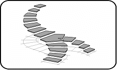
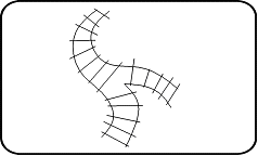
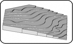
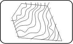
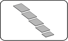
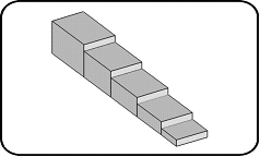
Originally, this command is used for modeling 3D stairs using any 2D draught, but it may also be used to generate a form of terrain as shown in the figure below:
|
|
|
"Stairs" steps |
|
|
|
"Terrain" steps" |
\steps
When you run this command, three options are offered:
Create Steps: Create steps by detecting the enclosed surfaces between the lines, arcs and curves joined on the same plane.
Continue Steps: Continue the steps of a series created previously using this command.
Modify Steps: Modify the height of each step.
Create steps
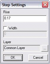
Use this option to start a new series of steps. Following dialogue box will appear:
|
|
In this dialog box, you can set: The height of each new step. The type of step. The width of the steps. The layer on which you want the series of steps to be displayed. |
To create a new series of steps, proceed in the following way:
Enter the desired height of the steps
Check the Width box and enter a value if you wish to set the "Stairs" steps. If this box is not checked, the steps created by default are "Terrain" steps:
|
|
|
|
"Stairs" |
"Terrain" |
Click the "…" button to display the layer management dialog box, from which you can select the layer on which you wish to create the new series of steps.
 HINT: In the layer management dialog box, click on the "Current" button in the bottom at the left of the dialog box to indicate the layer that is currently active...
Click OK to close the Configuration dialog box.
In the model, in the plan or axonometric view, click successively within all the enclosed surfaces for identifying the contour of every step. You can press Enter to access the usual parameterizing of the automatic detection of the enclosed surfaces.
When all the steps are identified, press Enter or Esc to exit the command.
 IMPORTANT: To optimize the detection of the enclosed surfaces, be careful that all the entities delineating them are on the same plane as the level z.
 NOTE: The series of steps thus created is a single and same object. If you try to delete it, ARC+ displays a dialog box asking you whether you wish to erase the selected entity only: Enter "Yes" to delete the selected step only and "No" to delete the entire series.
Continue Steps
Use this option to continue an existing series of steps. Proceed in following way:
It is recommended to go to the axonometric view to locate the entities composing the series to continue.
Indicate the polygon composing the upper face of the last step of the series to continue.
Proceed as for creating a new series while indicating the successive enclosed surfaces for identifying the contour of every step.
 NOTE: The system will only use the series of steps indicated as a reference level to start new steps. The result will contain two independent series of steps.
Modify Steps
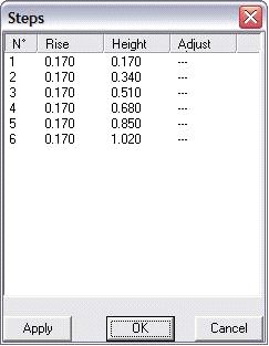
This option helps to change independently the height of the climbing line and level of every step of the same series. Preferably, present the model in axonometric view to work. After indicating the series of steps to modify, the following dialog box will appear:
|
|
Using this dialog box, you can: Verify every step once the series is finished. Verify the number of steps. Change the height of each step. Change the level of the upper face of several steps and calculate the intermediate elevations. Preview the changes. Apply the changes.
|
Description of columns
Rise: Indicates the height of the climbing line of the step.
Elevation: Indicates the level of the upper face of the step from z=0.
Adjust: Indicates the new height of elevation.
To modify the parameters of a step, proceed as follows:
Double-click on the number of step to modify in the column N. The adjacent dialogue box will appear.
 NOTE: The upper face of the selected step appears highlighted in orange
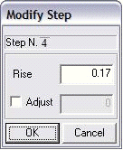
Enter the new height of the climbing line of the step in the field of Rise.
If you wish to change the height of step elevation, tick the Adjust check box and enter a value in the corresponding field.
Click OK
In the previous dialog box, click the Apply button to apply the changes to the model.
If you find the changes satisfactory, click OK, else click Cancel to abort the operation.
 NOTE: The displayed values are shown in the current working unit.

