Creating a 3D Array
Home > 09 Editing and Manipulation > Creating a 3D Array
Creating a 3D Array
Use this command to copy the selected entities, along 1, 2, or 3 major axes in a single operation, in order to generate an array. This command also enables to create a polar array on the XY plane.
\array3d
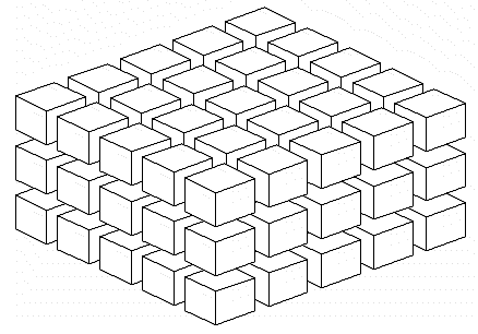
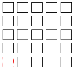
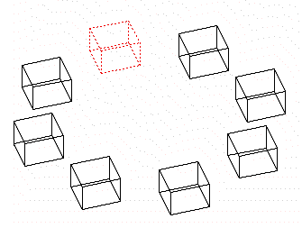
The examples given below illustrate the different types of networks that you can create with this command:
|
|
|
|
Array in Y
|
Array in XYZ |
|
|
|
|
Array in XY |
Polar Array |
After using this command, if no entity is selected, the system prompts you to define a capture fence between two points in which the entities to be duplicated will be selected.
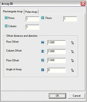
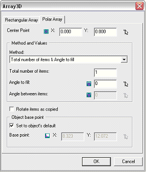
The following dialog box appears:
|
|
|
This dialog box has two tabs: one to define a rectangular array and the other to define a polar array.
 IMPORTANT: The two tabs of this dialog box contain numerical ranges to enter distances or angles. A small arrow appears in front of each of them, which helps to indicate the points in the model to calculate these values automatically:

Rectangular Array
The tab to define a rectangular array is divided into two main parts. You can use the upper part to enter the information related to the number of copies while the lower part can be used to set the positioning options.
|
OPTION |
DESCRIPTION |
|
Lines |
Number of copies along Y axis |
|
Columns |
Number of copies along X axis |
|
Floors |
Number of copies along Z axis |
|
Row offset |
Copy offset along Y axis |
|
Column Offset |
Copy offset along X axis |
|
Floor Offset |
Copy offset along Z axis |
|
Angle of array |
This value allows you to rotate the whole array with a specific angle. |
Polar Array
The tab to define a rectangular array is divided into three main parts: one to define the center point, one to select the construction method, and one for the rotation options.
Center point
The X and Y coordinates represent the point around which the elements should rotate
 NOTE: The Z coordinate is not to be specified because the elements can be rotated only on the XZ plane.
Method and value
The different construction methods depend on the parameters that you can enter:
Total number of elements: It represents the total number of elements that are found in the polar array.
Angle to be described: It is the total angle to be covered by all the elements.
Angle between elements: It is the angle between two elements. This value is expressed in degrees.
Rotation Options
When you activate the Rotate elements while copying option, the entities are rotated independently all along the polar array. In this case, the options to define the base point of these relative rotations can be accessed and changed. By default, the entities are rotated around the base point of the object. It is however possible to define another point by indicating these coordinates.


