Creating Running Dimensions
Home > 19 Dimensions > Creating Running Dimensions
Creating Running Dimensions
Label a drawing with running dimensions.
\rndim
Description
This command measures running dimensions (e.g. floor height) parallel to the vertical axis of a drawing.
The command is intended for use on a two-dimensional projection of a model, for example an elevational view (see Files, Saving a 2D projection of the model, \save2d command).
 NOTE You can use this command on a three-dimensional model to measure running dimensions parallel to the Y axis only. The running dimension symbols are placed in the XY plane.
The terms employed in this command are defined as follows:
running dimension The relative coordinate of a point along the vertical axis.
reference point A point on the axis relative to which running dimensions are measured.
reference value The value of the running dimension at the reference point (e.g., 0.00).
absolute dimension The true coordinate of a point along the axis (e.g., height above sea level).
Defining a Running Dimension Symbol
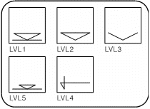
The command labels the running dimensions with a symbol from the dim_levl library. You can use one of the predefined symbols, or you can design your own symbol and add it to the library.
If you design a symbol, the first point you define is used as the justification point for dimension text, and the origin point is aligned with the measured running dimensions. Add the symbol to the library using the Saving a library file (\libedit) command (see Placing Objects & Libraries).
Operation
The first time you use this command in an ARC+ session, choose a running dimension symbol by typing its name or press Enter to view the graphic library. The next time you use the command, the same symbol is used by default or you may press Enter to choose a new symbol.


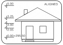
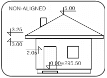
Choose whether to align the symbols vertically:
If you align, indicate an alignment point. The symbols are placed on an imaginary vertical line passing through the point.
If you do not align, the symbols are placed at points you indicate.
Indicate the reference point. Press Enter to use the alignment point as the reference point.
Type the reference value or press Enter for 0.00.
Type the absolute dimension of the reference point. Press Enter for no absolute value.
Press Enter if you want to place the first symbol at the reference point. The reference and absolute values are converted to the current dimension units (see Setting attributes, \adim command) and are displayed next to the symbol. The attributes are also taken from the current dimension attribute settings.
Indicate dimension points.
Before indicating any dimension point, you can change the size and orientation of the symbol:
|
Press |
Effect |
|
[Alt+1] |
Flip symbol about vertical axis |
|
[Alt+2] |
Flip symbol about horizontal axis |
|
[Alt+5] |
Increase size of symbol by a fixed increment |
|
[Alt+6] |
Decrease size |
|
[Alt+7] |
Change back to original size and orientation |
|
Enter |
Change size increment |
The running dimension of each point is written in the drawing.
 NOTE This command is affected by settings in the Setting attributes (\adim) command but cannot be updated by the Updating dimension attributes (\uadim) command.

